2004 Cadillac XLR: Service Information: Fuel Tank System
Estimated Reading Time: 13 MinutesCorvette and Cadillac XLR
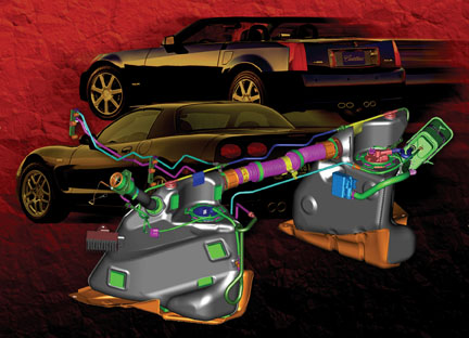
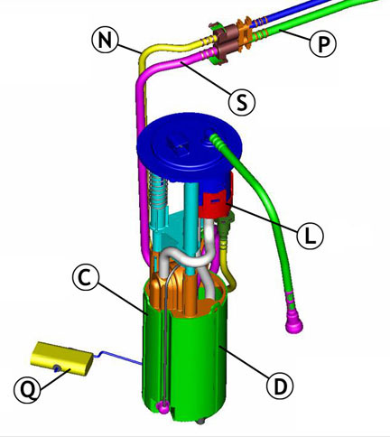
Partway through model year 2003, a new fuel tank system was introduced on the Corvette (fig. 1). This system continues with slight differences in the 2004 Corvette and Cadillac XLR.
TIP: For 2003 Corvettes only, this system was designated by RPO code FFS. However, this name has been unofficially applied to all vehicles with the new system.
Advantages and Features
The new fuel tank system was designed to accommodate future LEV 2 emission requirements. This was accomplished by moving as many components and fuel lines as possible inside the fuel tanks, to minimize hydrocarbon emissions. A flexible metal crossover hose assembly replaces the former rubber one, because the permeable rubber allowed a small amount of hydrocarbon to pass through.
The redesign also includes more isolation and noise control for the electric fuel pump, which now has greater flow capacity to supply higher output engines.
Component Layout
TIP: Use the reference letters to identify and locate the various components.
A Left side tank
B Right side tank
C Fuel sensor reservoir
D Turbine fuel pump
E Venturi pump
F Fuel fill hose
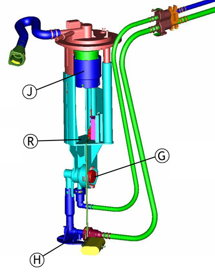
G Secondary fuel pressure regulator
H Siphon jet pump
J FLVV
K Crossover hose
L Filter
M Fuel feed pipe to engine
N Fuel feed pipe to RH tank
P Fuel return pipe to LH tank
Q Left fuel level sensor
R Right fuel level sensor
S Anti-siphon hole
T Fuel pump speed control module
U EVAP canister
V Primary fuel pressure regulator
W Check valve
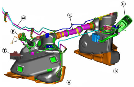
TIP: On the XLR only, a speed control module (T) slows the fuel pump when the engine is idling, to further control pump noise.
Two fuel tanks are used, and they’re joined by crossover plumbing (fig. 2 and fig. 3). The left side (driver side) tank (A) is considered the primary, and the right side (passenger side) is secondary (B).
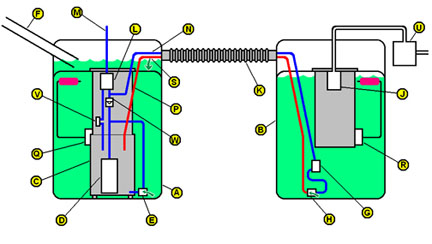
Each tank contains a sensor module, which includes a float and resistor card.
On the left side, the sender module includes a reservoir (C), containing the turbine fuel pump (D). There’s also a primary fuel pressure regulator (V) and a venturi pump (E). The left tank is also supplied by the fuel fill hose (F), and has a rollover vent valve.
On the right side, the sender module contains a secondary fuel pressure regulator (G) and a siphon jet pump (H). There is also a fill limiting vent valve (FLVV) (J).
Operation
When the fuel tanks are filled, fuel first fills the left tank. As the fuel rises to the level of the crossover (K), fuel flows into the right tank. As fuel occupies the interconnected tanks, air is forced to vent from the tanks, through the FLVV in the right tank. When both tanks are full, the FLVV float in the right tank closes, preventing fuel from entering the vent system. This also causes fuel to back up in the fill hose, causing the gas pump nozzle to shut off.
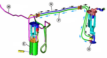
When the engine is running (fig. 4), the turbine fuel pump (D) in the left tank pressurizes the fuel feed pipe (M). The entire fuel supply system, from the pump to the injectors, is pressurized. The turbine pump creates more pressure and more fuel flow than the engine needs. Excess pressure and excess fuel is allowed to bleed back into the left tank by the primary fuel pressure regulator (V) within the tank.
TIP: The pressure regulator is in the fuel tank, not on the fuel rail on the engine. This type of fuel system is called returnless, or demand. This means that excess fuel is diverted before it leaves the tank, instead of passing through the fuel rail before being diverted. The result is that hot fuel is not constantly returning from the engine compartment, so the fuel in the tank stays cooler, improving evaporative emissions.
The majority of the pressurized fuel is directed through the filter (L) and on to the fuel feed pipe (M) to the engine, where it is injected into the cylinders for combustion.
Some of the pressurized fuel is directed through a feed pipe (N) inside the crossover hose, to a siphon jet pump in the right tank. The jet pump relies on the venturi effect to use pressurized fuel to draw additional fuel from the tank. The combined fuel then flows from the right tank to the left tank, through a return pipe (P) inside the crossover hose. The jet pump is able to move enough fuel to ensure that all of the fuel in the right tank is consumed before the level in the left tank begins to drop.
TIP: The return tube in the left tank has an anti-siphon hole (S), so the fuel in the left tank does not siphon back to the right side when the vehicle is shut down.
Some of the pressurized fuel is directed to a venturi pump in the left tank. This pump uses fuel flow to siphon fuel from the main tank into the reservoir, to keep the turbine pump supplied with fuel at all times. As the left tank fuel level drops, the venturi pump scavenges all of the remaining fuel into the reservoir, regardless of the vehicle’s attitude.
When the engine is shut off and the turbine pump stops, a reverse flow check valve (W) maintains pressure in the system to ensure rapid pressure buildup during the next startup cycle.
Operation of Fuel Level Gauge
When the fuel system is operating as designed, starting with both tanks full, the left tank will remain full until the right tank is depleted. Then the left tank will be emptied.
Each fuel tank has its own sensor (Q and R in the illustrations). Modules are shown in figure 5 (LH module) and figure 6 (RH module). The PCM supplies a reference of 5 volts to the two sensors. Each sensor operates across a range from full (2.5 volts) to empty (0.7 volts). The PCM monitors the fuel level sensor voltages and calculates how much fuel is in the two tanks. The readout of the IP fuel level gauge is a result of this calculation.
TIP: The fuel level sensors can be monitored with a Tech 2.
Several "zones" are used to describe various combinations of fuel levels in the two tanks.
Zone 1 -- The LH voltage is above its full threshold (typically calibrated to 2.4 volts) and the RH voltage is above its empty threshold (typically calibrated to 0.8 volts). Fuel volume = capacity of LH tank + volume in RH tank. This is the normal condition, before the fuel in the RH tank is completely consumed.
Zone 2 -- The LH voltage is above full threshold and RH is below empty threshold. This is also known as the deadband zone. Fuel volume = volume in LH tank + deadband volume - fuel used since entering zone. This is also a normal condition. It occurs because the actual amount of fuel in the tanks cannot be precisely indicated by the positions of the floats. That is, when the float reaches the top of its travel, it’s possible that the tank will hold additional fuel, which does not cause the float to move higher. Similarly, when the float reaches the bottom of its range, there may still be some fuel in the tank, and the float does not move any lower as the remaining fuel is consumed. So, the fuel in the bottom of the RH tank and the top of the LH tank will be consumed without either float moving. This is the "deadband."
Zone 4 -- The LH voltage is below full threshold value. Fuel volume = volume in LH tank. This condition occurs just after the zone 2 "deadband" is passed. All of the fuel is gone from the RH tank, and the LH sensor has begun to move down. The amount of fuel in the LH tank is all that remains.
Zone 5 -- The LH voltage is below its full threshold and the RH voltage is above its empty threshold. Fuel volume = volume in LH tank = volume in RH tank. This is a condition that should not occur in normal operation, because the RH tank should be consumed before the float in the LH tank begins to drop. If the fuel system is in zone 5 for a certain amount of time, a DTC (1431, 2066 or 2636) will set, and the fuel volume will be reported as zero by the fuel gauge.
A zone 5 condition could occur if the jet pump in the RH tank becomes clogged, preventing fuel from being siphoned from the RH tank. In this case, only fuel in the LH tank is available.
TIP: Service kits are available for each sensor, including:
- float
- wire arm
- wiper
- card
- card holder
Diagnostic Situations
The following situations may apply to the Corvette (C5), the Cadillac (XLR) or both, as noted.
Jet Pump Clog (C5, XLR) -- If the jet pump in the RH tank becomes clogged, fuel will not transfer to the LH tank. When this occurs, the vehicle eventually runs out of fuel, even though there is actually some in the RH tank. When the DTC (1431, 2066 or 2636) sets, the fuel gauge drops to empty and the customer perceives an "erratic gauge." One cause of this condition was a piece of plastic left in the jet pump during the manufacturing process. This has been remedied.
Fill Quality (C5) -- A customer may comment that the fuel nozzle shuts off prematurely, before the fuel tanks are full. The maximum flow rate for gas station pumps is supposed to be 10 gallons (37.9 L) per minute, and the fuel system is designed to accommodate this rate.
TIP: In reality, pump nozzles vary considerably in configuration, flow and shutoff sensitivity.
Ask the customer if the condition occurs at all stations, all the time, or at just one pump. This could point to a pump nozzle problem, not a vehicle problem.
Be sure the rubber hose to the canister vent solenoid (next to the transmission) is not restricted and that the vent solenoid is not stuck closed. Both can cause fuel to back up in the tanks and filler hose, causing the pump nozzle to shut off.
TIP:A replacement filler hose between the fill pipe and the LH fuel tank is available with a smaller inside diameter for C5. Although this sounds like it would make the condition worse, the smaller diameter allows less swirling, creating smoother fuel flow. A bulletin is pending.
Regulator Not Seated, Clip Loose (C5, XLR) -- If the clip retaining either regulator is not fully engaged, the fuel system will lose pressure and the vehicle may stall. This condition was remedied in production.
If the secondary regulator (right tank) is not seated, it could result in fuel not transferring from the right tank. It could also cause long crank times, because residual pressure is lost in the fuel feed pipe to the engine when the engine is shut down.
TIP: With the engine off, a pressure gauge connected at the fuel rail should indicate 52 psi (359 kPa). If pressure drops rapidly, the regulator may be unseated.
Open Fuel Level Sensor Circuit (C5, XLR) -- If an open occurs in a fuel level sensor circuit, the fuel gauge will drop to empty and a DTC will set. This could be caused by an unseated electrical terminal. Check the wiring circuits before replacing fuel system components. Another cause, which has been corrected, was the sensor wiper fingers not in contact with the resistor card, over the full sweep of the sensor.
TIP: The DTC specifies which sensor circuit has the issue. Only that sensor should be replaced.
LH Module Opening Too Small (C5, XLR) -- In some LH tanks, the module opening was undersized, making it difficult or impossible to remove the module. This has been corrected in production.
TIP: In any case, be careful of the sensor float wire when removing the module, to avoid damage.
Service Procedure Notes
TIP: Refer to IDL course 10260.22D, Technology Close-Up from October 2002, for additional information.
TIP: Always consult SI before performing a service procedure. The following are highlights and tips only.
Removing Fuel Tanks -- The crossover hose must be disconnected from a fuel tank which is being removed. The crossover is located above the driveline and exhaust system, making removal appear difficult. Both SI and the Labor Time Guide allow lowering the driveline and exhaust for access. See Driveline Support Assembly Replacement in SI. Once you have performed this procedure, you will gain enough knowledge of the components that you may be able to do the procedure in the future without lowering the driveline.
Crossover Hose -- The crossover hose is made of corrugated flexible stainless steel. It is retained to each fuel tank by a collar and a CPA (Connector Position Assurance). With the CPA aside, the collar can be turned by hand. It may be necessary to wiggle the crossover while pulling it straight out -- DO NOT TWIST.
The fuel feed and fuel return pipes for the transfer pump are inside the crossover, and are sealed with O-rings. The crossover is sealed to each tank with two O-rings. When installing the crossover, lube the O-rings and O-ring sealing surfaces with 1051717 rubber lubricant. Then align the pipes and push the crossover into place. DO NOT FORCE.
TIP:There is a T-shaped alignment feature (fig. 7) between the feed pipes which can be assembled only one way.
With the crossover in place, turn the collar. If the crossover and pipes are properly aligned and assembled, the collar can be turned with two fingers. Then snap the CPA into place.
Fuel Tank Module Replacement -- It is necessary to remove the fuel tank from the vehicle before removing the module. Procedures are different for LH and RH tanks.
TIP: Fuel Sensor Lock Ring Tool J-39765A is required.
When the lock ring is loosened, the module will spring upward, because it is spring-loaded to ensure it is bottom-referenced and to resist noise.
Follow the SI procedure exactly. It is necessary to disconnect and reconnect numerous fuel lines. The only access is through the module and crossover openings.
TIP: When the module is installed, be sure to check the empty and full readings of the fuel level sensor. Your DMM should read 40 ohms with the tank in vehicle orientation (simulating empty) and 250 ohms with the tank upside down (simulating full).
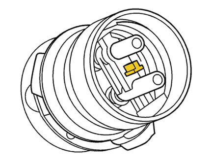
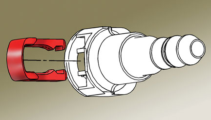
Fuel Line Quick Connectors
Fuel lines use quick connectors, described in the February 2004 TechLink. See page 6 for details.
TIP: To release, push on the retainer using hand pressure only. Do not attempt to remove it.
If the retainer becomes broken, it can be replaced (fig. 8) using the following part number.
|
5/16-inch (0.3125)
|
3/8- inch (0.375)
|
5/8-inch (0.625)
|
|
External vapor and internal liquid lines
|
Internal liquid lines
|
FLVV connector to the evap canister
|
|
214992748
|
22717568
|
21992746
|
Bulletin 02-06-04-010A -- This bulletin applies only to vehicles with the previous fuel system, which could be affected by fuel with an aggressive sulfur content. It does not apply to any XLR or 2003-04 Corvette with the FFS fuel system. DO NOT use this bulletin to justify reprogramming the PCM or replacing fuel sensors/modules in vehicles with the FFS fuel system.
TIP: In the new system, DO NOT reprogram the PCM unless specifically told to do so by a diagnostic procedure.
- Thanks to Dave Libby, Terry Stone and Dave Peacy, GM TechLink, March 2004
General Motors bulletins are intended for use by professional technicians, not a "do-it-yourselfer". They are written to inform those technicians of conditions that may occur on some vehicles, or to provide information that could assist in the proper service of a vehicle. Properly trained technicians have the equipment, tools, safety instructions and know-how to do a job properly and safely. If a condition is described, do not assume that the bulletin applies to your vehicle, or that your vehicle will have that condition. See a General Motors dealer servicing your brand of General Motors vehicle for information on whether your vehicle may benefit from the information.
© Copyright General Motors Corporation. All Rights Reserved
I donât see a mention of the fuel tank pressure sensor in any of this write up. I have heard itâs located in two places which I would like to know which one it is. I have found where itâs mention to be on the vapor canister inside the right rear inner fender liner. The second is that itâs located on the right side fuel tank. If you happen to know for sure I would greatly appreciate your insight.