I made that harder than it needed to be

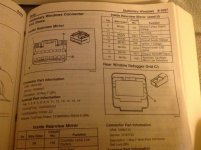
In the end, the ground (#8 - all blk) and ignition 1 voltage (#13 - blk/pink) pins are the same, but the wire colors are different than even the '06 manual info above - maybe there is a V vs. Base difference?
I found this "tool" (drawer knob) to be quite helpful in pulling out the plug - that bastard really sticks in there and there is nothing to grab onto (screwdriver, pliers, mashed fingers, and cursing were all unpersuasive). I used the lip of the screw head to catch onto the top of the latch.

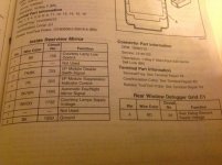
The first is a pic of the wire colors from the top, the second from the bottom. The view is from the back, so reverse left/right when comparing to the diagram above. You can see the differences in the colors for yourself, the ignition wire is pink/blk, not red/blk for me.
This seems like a stupid point to make, but the ignition wire - as name implies - will not supply voltage in accessory on mode, only with engine actually running - which makes voltage testing in a garage a bit of a problem.

I will also point out that the courtesy lamp supply voltage (#6 blk/orange for me too) will power a device with 12 volts, but does not turn off (even after the 20 min timeout) and will eventually drain the battery.


As luck would have it, I did not actually fry my radar,

but simply blew a fuse with my first unsuccessful attempt.
Live and learn... looks clean now!
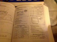
This is from the '06 Service Manual. I hope this helps.

Mike


 where the headlights would not turn off because the "auto-off" circuit board had a failing solder point.


